


Leaderboard


Popular Content
Showing content with the highest reputation on 03/20/2025 in all areas
-
Yes I would replace the flywheel if the magnet is no longer there. The pick-up coil on the stator when the magnet on the flywheel pass it give out a electric pulse and also determines the engine timing the ecu if there an issue with the timing then I would check the key way on the flywheel. Second I would check the camshaft timing to flywheel to determine that your valve timing is correct.1 point
-
Wow Ben... thanks for the comprehensive explanation. Thanks for taking the time, as you will have saved many the time and frustration in getting the engine timed correctly.1 point
-
BTW.......rocker shafts are removed by screwing in an 8mm??? bolt and then pulling on the bolt head and/or slide hammer. Rockers are then removed. You first need to check the possible sheared crankshaft key. Take a soft copper wire about 16" long and put a finger loop on one end. Stick the wire into the spark plug hole and rest on the piston dome.......slowly rotate the engine. The TDC on the crank should align when the copper wire is at it's highest point and will fall back from it's peak as you rotate back and forth at the TDC mark. I like to dab some paint on the crank to make the mark easily spotted when doing any timing jobs. Compare to the first pic. Leave at TDC. NOTE: There are 2 TDC with a 4 stroke engine.......720 deg of rotation. The position of the cam at TDC will determined if it is OVERLAP or compression/IGNITION/power . This has caught many a person on V-Twin engines that will run BUT be low power and the wrong exhaust note. Both cams are "TDC" and fire OK but they are not "phased" correctly. Short and Loooong intervals between the front and rear cylinders power strokes.....gives a lumpy sound. Yours is a single cylinder. Your timing was correct or off by one tooth. Your pic is shot at an angle so hard to tell. When you are putting the new head and cam on, inspect the cam assy. Get a good look at the cam and the compression release "mini cam". Slide in the cam with the lobes AWAY from the rocker slipper pads. REF your pic above........The longest RED ARROW aligns with the cam mounting bolt(s) and the cam gear punch mark which is hidden when assembled. It is UNDER one of those stamped thin step folded metal "keeper" for the flyweights. When the flyweights sling out with engine RPM rotation, it will turn the smaller round disc by way of the dual connecting pins. The cam gear timing mark (dimple) is under the upper (in your pic) keeper close to the teeth. Right below this bolt is the timing mark for the compression release mini cam.....the quarter sized CENTER disc in your pic. It is just barely showing (about half of the dimple circle) adjacent to the RH side of your RED ARROW. This dimple should align with the cam gear dimple....NOTE: It can be put in 180 deg out relative to the valve cam. I always put a dab of white paint on the cam gear timing mark with a little smear almost up to the teeth (on the machined rim) so you can see the timing mark AFTER the keepers are installed under the cam mounting bolts. Timing alignment: (1) TDC mark on the flywheel at case mark WITH the slack taken out of the tensioner side of the cam chain (no tensioner installed yet) along with (2) cam gear paint mark AND and the dimple in the center disk (compression release mechanism). Install tensioner and "hand" crank (turn over) the crank to ckeck for binds. Special note to NOT adjust the valve clearance when the cam is on the compression release ball. Hand turn the crank to the TDC and at slow RPM (as in hand crank) the flyweights will be pulled in with the springs (the compression release is active and holding the exhaust valve slightly open with a small ball under the exhaust rocker.........will give the wrong valve adjustment. Continue turning in the direction of rotation until the ball clears the rocker (recess back into the hollow cam center). Finger tighten the adjustment screw to ZERO clearance and reverse the rotation. When the compression release ball starts to get under the cam, it will "lock up the flyweights". Manually rotate the flyweights to the extended rotation (RUN) position and your should be able to reverse the motor/cam even more. When close to TDC, adjust to spec clearance. The extra step above seems to be extra and not needed but what you are looking for is a bad batch of compression release cams....... the flyweights did not collapse to the fully closed position. I had these cam problems also in the Yam Rhino (identical weight tab welds and tooling cuts (same OEM???) and my modified cam (my personal shelf stock) given away to fix a Rhino. My modification was the grind the excess material on the welded on tab to give the rest of the clearance at where it rubbed the compression release "quarter sized " disc. Covered in an earlier BEN 1098 post.1 point
-

263 downloads
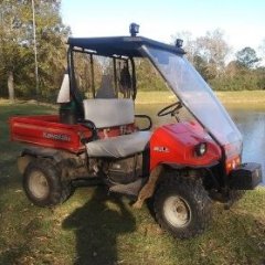
This is a complete service manual for the Kawasaki Mule 500,520 and 550 models. Topics covered include Brakes, Steering, Electrical system, suspension and fuel system. As well as engine repair procedures and Transmission/Final Drive procedures. ******************************************************************************************************************************************************************************************** If you need more information about the engine this manual linked below is chock full of information. Thanks goes to @cliffyk for getting these files all into one PDF format for uploading.1 point
This leaderboard is set to New York/GMT-04:00